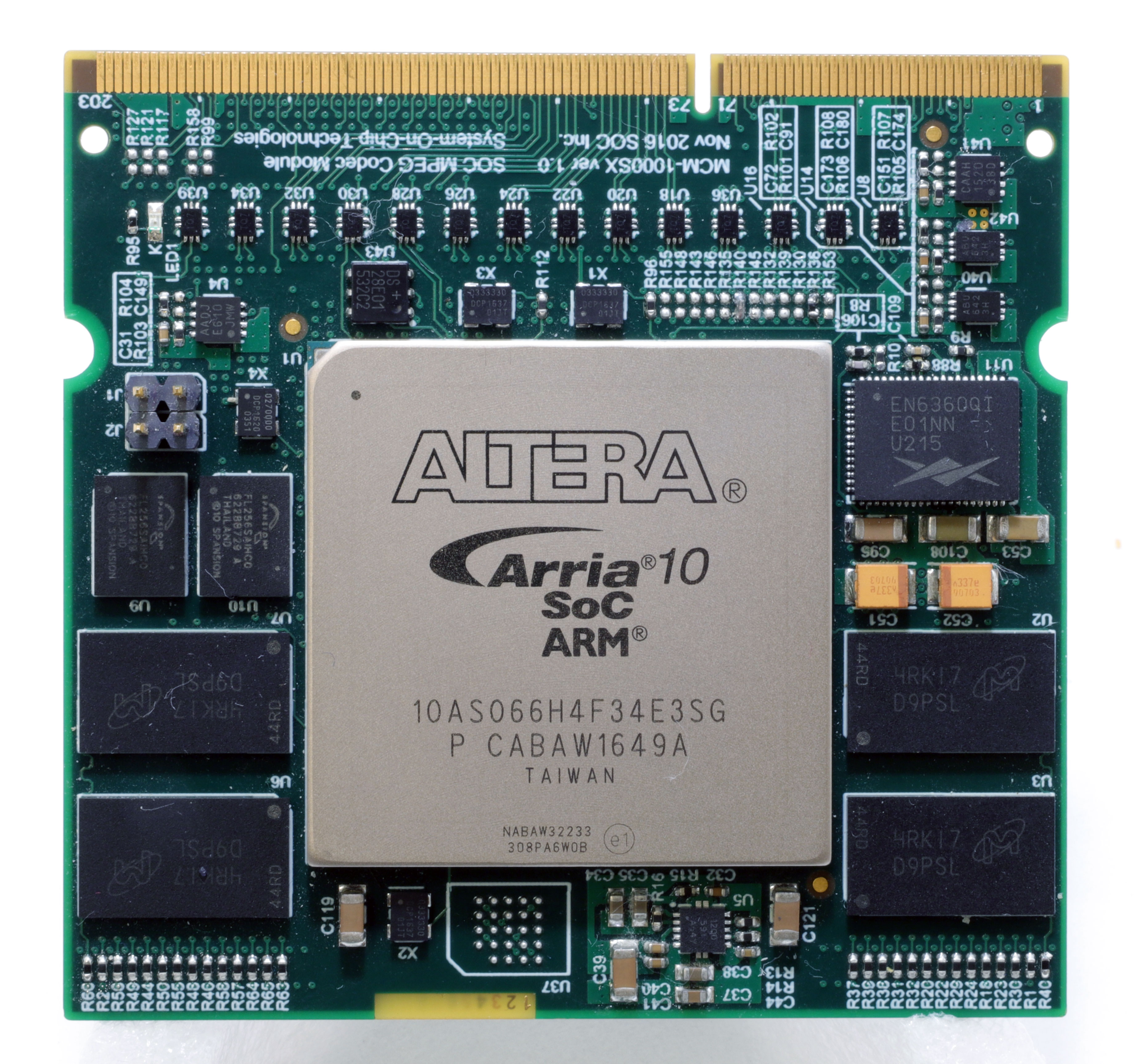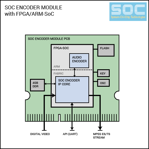
SOC Mpeg Codec Modules (MCMs) are small yet powerful video processing PCBs designed to reduce the engineering effort needed to make use of our low-latency all-hardware video/audio Codec IP.
MCM Modules are built with all the IC and interfaces that our Codec IP cores need to process real-time video:
- a high-performance Xilinx/Intel FPGA/SoC
- DDR memory
- Flash/EEPROM
- Audio-codec capabilites
- Run-time API interface
MCM modules are pre-loaded with firmware according to customer specifications. They are shipped as ready to use, plug-in-and-play Codec processing systems.
To use MCM modules, add a 204-pin card connector on your PCB, and you are ready to encode/decode/transcode up to 4K/60 video (3840x2160 at 60fps), at ultra-low latencies (as low as 0.25ms!).

- Specifications
Codec Function : Encoding Compression Standard : H.265/HEVC Channels : One Precision : 10 bits per channel Max. Framerate : Up to 30 FPS (30/29.97, 25/24.97, 24/23.98...) Max. Resolution : Up to 4K/UHD (3840x2160) Codec FPGA : Intel SX660 - Components
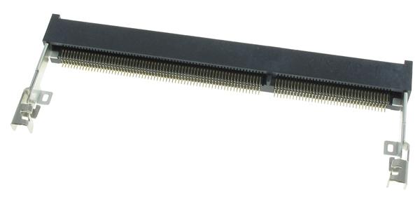
MCM Modules interface to user PCBs via a standard 204-pin SODIMM connector. You may recognize this connector as the DDR3 SDRAM connector used for connecting high-speed RAM to PCs. Coincidentally, this connector is also well-suited for streaming uncompressed and compressed video data.
You may purchase this connector from various electronics parts suppliers:
MM80 Series Inline Module Socket Connector
Manufacturer: JAE Electronics204-pin DDR3 SDRAM SODIMM Connector
Manufacturer: TE Connectivity AMP Connectors
Working reference designs may be licensed from System-On-Chip Technologies.
4K video is transmitted as four synchronized HD quadrants.
Video data is transferred on HDMII_D[] and VIDEO_C[] data busses. VIDEO_VS (vertical sync) and VIDEO_HS (horizontal sync) signals are used for frame synchronization.
10-bit capable systems use 10 bits per channel, 8-bit systems ignore the 2 lowest bits [1:0] (they can be set to '0').
| Signal Name | Dir. | Description |
|---|---|---|
| VIDEO_HS | O | Horizontal-Sync |
| VIDEO_VS | O | Vertical-Sync |
| VIDEO_CLK_0 | O | Quadrant-0 (top-left, primary) Video Clock |
| VIDEO_Y[9:0] | O | Q-0 Luma |
| VIDEO_C[9:0] | O | Q-0 Chroma |
| VIDEO_CLK_1 | O | Quadrant-1 (top-right) Video Clock |
| VIDEO_Y[19:10] | O | Q-1 Luma |
| VIDEO_C[19:10] | O | Q-1 Chroma |
| VIDEO_CLK_2 | O | Quadrant-2 (bottom-left) Video Clock |
| VIDEO_Y[29:20] | O | Q-2 Luma |
| VIDEO_C[29:20] | O | Q-2 Chroma |
| VIDEO_CLK_3 | O | Quadrant-3 (bottom-right) Video Clock |
| VIDEO_Y[39:30] | O | Q-4 Luma |
| VIDEO_C[39:30] | O | Q-4 Chroma |
VIDEO_CLK is driven by the video source (usually HDMI or SDI chipset). VIDEO_CLK frequency should be set according to the resolution and framerate of the video source:
| Resolution /FPS | Clock Frequency |
|---|---|
| 640x480p 60fps | 27 Mhz |
| 1280x720p 60fps | 74.25 Mhz |
| 1920x1080p 30fps | 74.25 Mhz |
| 1920x1080p 60fps | 148.5 Mhz |
Compressed data is transferred as an 8-bit stream over TS_BYTE[7:0] lines. At every rising edge of TS_CLK, if TS_DV is '1', this means that the current data on the TS_DATA bus is valid for reading.
| Signal Name | Dir. | Description |
|---|---|---|
| TS_CLK | O | Stream Clock |
| TS_RDY | I | Receiver Ready |
| TS_DV | O | Data Valid |
| TS_BYTE[7:0] | O | Stream Data |
Modules expose a serial UART interface for reading/writing API registers. For a list of available API registers, refer to the API Guide.
| Signal Name | Dir. | Description |
|---|---|---|
| UART_RX | I | UART data to module |
| UART_TX | O | UART data from module |
The standard UART protocol uses these parameters:
| Baudrate | Data bits | Start bits | Stop bits | Parity bits |
|---|---|---|---|---|
| 115200 | 8 | 1 | 1 | 0 |
Working reference designs may be licensed from System-On-Chip Technologies.
